


AV Connection Diagram vs Signal Flow Diagram: What's the Difference?
In audiovisual system integration, understanding the distinction between an av connection diagram and a signal flow diagram is crucial for project success. An av connection diagram shows the physical wiring between AV equipment, including specific cable types, connectors, and routing paths needed for installation. In contrast, a signal flow diagram illustrates the logical path that audio signals, video signals, and control data take through the system, focusing on processing and functionality rather than physical implementation.
The importance of proper documentation extends to the tools used for creation. Modern AV integrators increasingly rely on best free wiring diagram software and specialized AV design platforms that streamline both diagram types, reduce errors, and integrate with project workflows. According to industry research, AV projects documented with professional software experience 60% fewer installation errors and complete 40% faster than manual methods, making the right documentation approach essential for competitive advantage in 2026.
Key Takeaways
Connection diagrams show physical wiring (cables, connectors, routing); signal flow diagrams show logical signal paths and processing
Professional AV projects require both diagram types for complete documentation serving different stakeholders
Installation technicians need connection diagrams; operators and programmers need signal flow diagrams
Modern AV design software streamlines creation of both types with automation and validation features
Common mistakes include using wrong diagram type for specific tasks and failing to maintain as built documentation
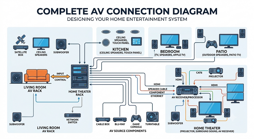
What Is an AV Connection Diagram?
An av connection diagram serves as the technical blueprint for physical AV system installation, detailing how every device connects within the infrastructure. This documentation focuses exclusively on the physical layer, providing comprehensive information about cables, connectors, and hardware interfaces.
Essential components include:
Equipment identification with manufacturer and model numbers
Cable specifications (type, length, gauge, shielding)
Connector types at both termination points
Port assignments matching equipment labels
Cable routing through conduits and infrastructure
Rack positions for mounted equipment
Power distribution and grounding details
These diagrams answer one fundamental question for installation crews: "How do we physically wire this system?" They transform abstract designs into actionable installation instructions, reducing errors and ensuring consistent implementation. For professionals planning equipment organization, understanding how to create a small AV rack diagram before installation provides essential pre-installation planning guidance.
What Is a Signal Flow Diagram?
A signal flow diagram focuses on logical signal paths through the AV system, illustrating how audio, video, and control signals move from sources through processing to destinations. Unlike connection diagrams emphasizing physical implementation, signal flow diagrams explain system functionality and operation.
Key elements include:
Signal sources and input devices
Processing blocks (mixing, switching, scaling, conversion)
Signal transformations and format changes
Routing options and switching logic
Control relationships and automation
Destination devices and outputs
These diagrams answer the operational question: "How does this system actually work?" They help control programmers implement logic, enable operators to use systems effectively, and guide troubleshooting of functional issues.
AV Connection Diagram vs Signal Flow Diagram: Key Differences
Aspect | AV Connection Diagram | Signal Flow Diagram |
Focus | Physical implementation | Logical functionality |
Details | Cable specs, connectors, lengths | Signal types, processing, routing |
Users | Installers, technicians | Operators, programmers |
Purpose | Installation guidance | Operation understanding |
Updates | Physical changes | Functionality changes |
Connection diagrams remain concrete with specific cable part numbers, exact lengths, and physical routing. Signal flow diagrams embrace abstraction, representing functional blocks and logical relationships regardless of physical layout. Both describe the same system from necessary but different perspectives. |
When Should You Use an AV Connection Diagram?
Connection diagrams are critical during:
Installation phase: Providing material procurement details, cable pulling guidance, equipment mounting instructions, and quality control verification.
System troubleshooting: Tracing physical connectivity issues, verifying correct connections, identifying cable damage locations, and checking proper terminations.
Modification planning: Understanding current connections before changes, assessing available capacity, and planning integration points with existing infrastructure.
Compliance requirements: Demonstrating code compliance, meeting client deliverables, and supporting warranty documentation according to AVIXA installation standards.
When Should You Use a Signal Flow Diagram?
Signal flow diagrams prove essential for:
Design validation: Confirming systems meet functional requirements, explaining capabilities to clients, and coordinating between designers and programmers.
Control programming: Understanding required signal routing, identifying switching logic, planning preset configurations, and designing user interfaces. Resources about why XTEN-AV is the best schematic drawing program for AV integrators highlight how specialized tools streamline signal flow documentation.
Training and operation: Teaching system usage, creating operational manuals, and providing quick reference guides for end users.
Functional troubleshooting: Diagnosing routing problems, verifying processing operations, and understanding automatic behaviors.
Why Most AV Projects Need Both
Professional AV integration projects require both diagram types because they serve complementary roles. Connection diagrams ensure systems can actually be built, addressing physical constraints and providing installation instructions. Signal flow diagrams ensure systems meet functional expectations, validating operational logic and user requirements.
Different stakeholders need different information: installation technicians need precise connection details, control programmers need comprehensive signal flow understanding, end users need operational explanations, and service technicians need both depending on problem type. According to AVIXA 2026 standards, projects with both diagram types complete 35% faster than those with incomplete documentation.
Common Mistakes AV Professionals Make
Using signal flow diagrams for installation: Providing installers with only signal flow diagrams lacking cable specifications leads to constant field questions and errors.
Over complicating connection diagrams: Including excessive functional information clutters diagrams and obscures critical physical details installers actually need.
Failing to update as built documentation: Not updating diagrams to reflect field changes creates troubleshooting nightmares and future modification complications.
Using wrong tools: Creating professional diagrams with PowerPoint or Paint results in unprofessional deliverables. Use appropriate AV design software or best free wiring diagram software designed for audiovisual applications.
Benefits of Using AV Design Software for Both Diagrams
Modern AV design software delivers substantial advantages:
Unified equipment libraries: Single device entry appears in both diagram types, eliminating duplicate work and ensuring consistency.
Intelligent automation: Smart cable routing, connector validation, automatic numbering, and cable length calculation reduce creation time by 50 to 70%.
Automated documentation: Generate cable schedules, bills of materials, operational guides, and testing checklists automatically from diagrams.
Collaboration features: Cloud platforms enable multi user access, real time synchronization, version control, and mobile field access. Understanding integrating schematic drawing software with AV project management platforms demonstrates how seamless workflows enhance productivity.
Time and cost savings: Professional software reduces engineering time, minimizes installation errors, improves project capacity, and delivers ROI within three to six months.
Why XTEN-AV Makes Both Diagram Types Easy
XTEN AV offers comprehensive capabilities for both connection and signal flow diagrams through its integrated platform. The unified environment creates all diagram types with shared equipment libraries, seamless switching between views, and coordinated documentation that maintains consistency.
Intelligent features include smart cable routing finding optimal paths automatically, connector validation preventing incompatible connections, automatic labeling with customizable schemes, and real time validation catching errors during design. AI powered capabilities in 2026 provide automated layout optimization, intelligent error detection, and natural language documentation generation.
Best Practices for Creating Professional AV Diagrams
Plan before drawing: Gather complete information, define documentation standards, and consider audience needs before creating diagrams.
Maintain consistency: Use identical equipment names across diagram types, apply consistent color coding and symbols, and coordinate updates between diagrams.
Use appropriate detail: Include necessary information for intended users without cluttering diagrams with irrelevant details.
Document as built conditions: Track field changes systematically, update diagrams before project closeout, and maintain clear version control.
Leverage software capabilities: Utilize automation, collaboration features, validation tools, and integration with project management systems.
How X-DRAW Simplifies AV Connection and Signal Flow Diagrams
X DRAW, the diagramming engine within XTEN AV, transforms diagram creation through intelligent auto routing that finds optimal cable paths automatically, unified equipment databases maintaining consistency, automated documentation generation, real time validation catching errors, and flexible visualization adapting to user needs.
AI enhanced features reduce creation time by 40 to 50% compared to manual methods while improving accuracy and enabling team collaboration through cloud integration and multi user editing capabilities.

Why Every AV Integrator Needs Wiring Diagram Software in 2026
Modern AV systems in 2026 feature unprecedented complexity with network based architectures, AV over IP implementations, and sophisticated IoT integration. Professional wiring diagram software has evolved from optional to essential for managing this complexity effectively.
Industry challenges including skilled labor shortages, productivity pressures, and rising client expectations make software efficiency critical. Integration companies leveraging professional tools report 30 to 40% higher project volume with the same engineering headcount, creating significant competitive advantages.
AI powered automation in 2026 provides design suggestions, intelligent error detection, and predictive analytics that deliver 25 to 35% additional efficiency gains beyond traditional tools, positioning adopters as industry leaders.
Frequently Asked Questions (FAQs)
What is the main difference between an AV connection diagram and signal flow diagram?
An av connection diagram shows physical wiring including cable types, connectors, and routing for installation. A signal flow diagram illustrates logical signal paths showing processing and functionality for operation understanding. Connection diagrams serve installers; signal flow diagrams serve operators and programmers.
Can I use one diagram type for both purposes?
No, each serves distinct purposes. Connection diagrams lack operational logic installers do not need. Signal flow diagrams lack physical specifications installers require. Professional projects need both types serving their respective stakeholders.
What software should I use for AV diagrams?
Specialized AV design software like XTEN AV or similar platforms deliver best results through AV specific libraries, intelligent automation, and workflow integration, achieving ROI within three to six months through efficiency gains.
How detailed should connection diagrams be?
Include sufficient detail for qualified technicians to complete work without additional instructions: equipment models, cable specifications, connector types, port assignments, routing paths, and installation notes.
Do simple projects need both diagram types?
Simple single source to display systems may need only basic connection diagrams. Systems with multiple sources, switching, processing, or control benefit from both types for complete documentation.
How often should I update diagrams?
Update whenever physical or functional changes occur. Create as built versions during installation, finalize after commissioning, and maintain throughout system lifecycle with clear version control.
Can AI help create AV diagrams?
Yes, AI powered features in 2026 provide automated layout optimization, intelligent routing, error detection, and documentation generation that reduce creation time and improve quality significantly.
Conclusion
Understanding the distinction between av connection diagrams and signal flow diagrams is fundamental for AV integration success. Connection diagrams guide physical installation with detailed cable and connector specifications, while signal flow diagrams explain system functionality with logical signal paths and processing details. Both are essential for complete project documentation serving different stakeholders throughout the lifecycle.
Modern AV design software with AI powered features transforms diagram creation through automation, validation, and collaboration capabilities that deliver substantial competitive advantages. As systems grow more complex in 2026, professional tools become essential rather than optional for efficient, accurate documentation.
Invest in appropriate software, follow best practices, maintain both diagram types, and create documentation worthy of professional AV systems. Your installers, programmers, operators, and clients will benefit from comprehensive documentation supporting successful project delivery and long term system operation.



Comments